Balbharti Maharashtra State Board 12th Physics Textbook Solutions Chapter 12 Electromagnetic Induction Textbook Exercise Questions and Answers.
Electromagnetic Induction Class 12 Exercise Question Answers Solutions Maharashtra Board
Class 12 Physics Chapter 12 Exercise Solutions Maharashtra Board
Physics Class 12 Chapter 12 Exercise Solutions
1. Choose the correct option.
i) A circular coil of 100 turns with a cross-sectional area (A) of 1 m2 is kept with its plane perpendicular to the magnetic field (B) of 1 T. What is the magnetic flux linkage with the coil?
(A) 1 Wb
(B) 100 Wb
(C) 50 Wb
(D) 200 Wb
Answer:
(B) 100 Wb
ii) A conductor rod of length (l) is moving with velocity (v) in a direction normal to a uniform magnetic field (B). What will be the magnitude of induced emf produced between the ends of the moving conductor?
(A) BLv
(B) BLv2
(C) \(\frac{1}{2}\)Blv
(D) \(\frac{2 B l}{\mathrm{v}}\)
Answer:
(A) BLv
![]()
iii) Two inductor coils with inductance 10 mH and 20 mH are connected in series. What is the resultant inductance of the combination of the two coils?
(A) 20 mH
(B) 30 mH
(C) 10 mH
(D) \(\frac{20}{3}\) mH
Answer:
(A) 20 mH
iv) A current through a coil of self inductance 10 mH increases from 0 to 1 A in 0.1 s. What is the induced emf in the coil?
(A) 0.1 V
(B) 1 V
(C) 10 V
(D) 0.01 V
Answer:
(A) 0.1 V
v) What is the energy required to build up a current of 1 A in an inductor of 20 mH?
(A) 10 mJ
(B) 20 mJ
(C) 20 J
(D) 10 J
Answer:
(A) 10 mJ
2. Answer in brief.
i) What do you mean by electromagnetic induction? State Faraday’s law of induction.
Answer:
The phenomenon of production of emf in a conductor or circuit by a changing magnetic flux through the circuit is called electromagnetic induction.
Faraday’s laws of electromagnetic induction :
(1) First law ; Whenever there is a change in the magnetic flux associated with a circuit, an emf is induced in the circuit.
(2) Second law : The magnitude of the induced emf is directly proportional to the time rate of change of magnetic flux through the circuit.
[Note : The phenomenon was discovered in 1830 by Joseph Henry (1797-1878), US physicist, and independently in 1832 by Michael Faraday (1791 -1867), British chemchemist and physicist.]
ii) State and explain Lenz’s law in the light of principle of conservation of energy.
Answer:
Lenz’s law : The direction of the induced current is such as to oppose the change that produces it.
The change that induces a current may be (i) the motion of a conductor in a magnetic field or (ii) the change of the magnetic flux through a stationary circuit.
Explanation : Consider Faraday’s magnet-and- coil experiment. If the bar magnet is moved towards the coil with its N-pole facing the coil, as in Fig., the number of magnetic lines of induction (pointing to the left) through the coil increases. The induced current in the coil sets up a magnetic field of its own pointing to the right (as given by Amperes right-hand rule) to oppose the growing flux due to the magnet. Hence, to move the magnet towards the coil against this repulsive flux of the induced current, we must do work. The work done shows up as electric energy in the coil.
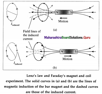
When the magnet is withdrawn, with its N-pole still facing the coil, the number of magnetic lines of induction (pointing left) through the coil decreases. The induced current reverses its direction to supplement the decreasing flux with its own, as shown in Fig.. Facing the coil along the magnet, the induced current is in the clockwise sense. The electric energy in the coil comes from the work done to withdraw the magnet, now against an attractive force. Thus, we see that Lenz’s law is a consequence of the law of conservation of energy.
[Note : The above law was discovered by Heinrich Friedrich Emil Lenz (1804-65), Russian physicist.]
![]()
iii) What are eddy currents? State applications of eddy currents.
Answer:
Whenever a conductor or a part of it is moved in a magnetic field “cutting” magnetic field lines, or placed in a changing magnetic field, the free electrons in the bulk of the metal start circulating in closed paths equivalent to current-carrying loops. These loop currents resemble eddies in a fluid stream and are hence called eddy or Foucault currents [after Jean Bernard Leon Foucault (1819-68), French physicist, who first detected them].
Applications :
(1) Dead-beat galvanometer : A pivoted moving-coil galvanometer used for measuring current has the coil wound on a light aluminium frame. The rotation of the metal frame in magnetic field produces eddy currents in the frame which opposes the rotation and the coil is brought to rest quickly. This makes the galvanometer dead-beat.
(2) Electric brakes : When a conducting plate is pushed into a magnetic field, or pulled out, very quickly, the interaction between the eddy currents in the moving conductor and the field retards the motion. This property of eddy currents is used as a method of braking in vehicles.
iv) If the copper disc of a pendulum swings between the poles of a magnet, the pendulum comes to rest very quickly. Explain the reason. What happens to the mechanical energy of the pendulum?
Answer:
As the copper disc enters and leaves the magnetic field, the changing magnetic flux through it induces eddy current in the disc. In both cases, Fleming’s right hand rule shows that opposing magnetic force damps the motion. After a few swings, the mechanical energy becomes zero and the motion comes to a stop.
Joule heating due to the eddy current warms up the disc. Thus, the mechanical energy of the pendulum is transformed into thermal energy.
v) Explain why the inductance of two coils connected in parallel is less than the inductance of either coil.
Answer:
Assuming that their mutual inductance can be ignored, the equivalent inductance of a parallel combination of two coils is given by
\(\frac{1}{L_{\text {parallel }}}=\frac{1}{L_{1}}+\frac{1}{L_{2}}\) or Lparallel = \(\frac{L_{1} L_{2}}{L_{1}+L_{2}}\)
Hence, the equivalent inductance is less than the inductance of either coil.
Question 3.
In a Faraday disc dynamo, a metal disc of radius R rotates with an angular velocity ω about an axis perpendicular to the plane of the disc and passing through its centre. The disc is placed in a magnetic field B acting perpendicular to the plane of the disc. Determine the induced emf between the rim and the axis of the disc.
Answer:
Suppose a thin conducting disc of radius R is rotated anticlockwise, about its axis, in a plane perpendicular to a uniform magnetic field of induction \(\vec{B}\) (see the figure in the above Note for reference). \(\vec{B}\) points downwards. Let the constant angular speed of the disc be ω.
Consider an infinitesimal element of radial thickness dr at a distance r from the rotation axis. In one rotation, the area traced by the element is dA = 2πrdr. Therefore, the time rate at which the element traces out the area is
\(\frac{d A}{d t}\) = frequency of rotation x dA = fdA
where f = \(\frac{\omega}{2 \pi}\) is the frequency of rotation.
.’. \(\frac{d A}{d t}=\frac{\omega}{2 \pi}\) (2 πr dr) = ωr dr
The total emf induced between the axle and the rim of the rotating disc is
\(|e|=\int B \frac{d A}{d t}=\int_{0}^{R} B \omega r d r=B \omega \int_{0}^{R} r d r=B \omega \frac{R^{2}}{2}\)
For anticlockwise rotation in \(\vec{B}\) pointing down, the axle is at a higher potential.
![]()
Question 4.
A horizontal wire 20 m long extending from east to west is falling with a velocity of 10 m/s normal to the Earth’s magnetic field of 0.5 × 10⁻⁴ T. What is the value of induced emf in the wire?
Answer:
Data : l = 20 m, v = 10 m/s. B = 5 × 10⁻⁵ T
The magnitude of the induced emf,
|e| = Blv = (5 × 10⁻⁵)(20)(10) = 10-2V = 10 mV
Question 5.
A metal disc is made to spin at 20 revolutions per second about an axis passing through its centre and normal to its plane. The disc has a radius of 30 cm and spins in a uniform magnetic field of 0.20 T, which is parallel to the axis of rotation. Calculate
(a) The area swept out per second by the radius of the disc,
(b) The flux cut per second by a radius of the disc,
(c) The induced emf in the disc.
Answer:
Data: R = 0.3m, f = 20 rps, B = 0.2T
(a) The area swept out per unit time by a given radius = (the frequency of rotations) × (the area swept out per rotation) = f(πr2)
= (20)(3.142 × 0.09) = 5.656 m2
(b) The time rate at which a given radius cuts magnetic flux
= \(\frac{d \Phi_{\mathrm{m}}}{d t}\) = B f(πr2)
= (0.2)(5.656) = 1.131 Wb/s
(c) The magnitude of the induced emf,
|e| = \(\frac{d \Phi_{\mathrm{m}}}{d t}\) = 1.131 V
Question 6.
A pair of adjacent coils has a mutual inductance of 1.5 H. If the current in one coil changes from 0 to 10 A in 0.2 s, what is the change of flux linkage with the other coil?
Answer:
Data: M = 1.5 H, I1i = 0, I1f = 10A, ∆f = 0.2s
The flux linked per unit turn with the second coil due to current I1 in the first coil is
Φ21 = MI1
Therefore, the change in the flux due to change in I1 is
∆21 =M(∆I1) = M(I1f – I1i) = 1.5 (10 – 0)
= 15 Wb
[Note: The rate of change of flux linkage is M(∆I1/∆t) = 15/0.2 = 75 Wb/s] .
![]()
Question 7.
A long solenoid has 1500 turns/m. A coil C having cross sectional area 25 cm2 and 150 turns (Nc) is wound tightly around the centre of the solenoid. If a current of 3.0A flows through the solenoid, calculate :
(a) the magnetic flux density at the centre of the solenoid,
(b) the flux linkage in the coil C,
(c) the average emf induced in coil C if the direction of the current in the solenoid is reversed in a time of 0.5 s. (µ0 = 4π × 10-7 H/m)
Answer:
Data: n = 1.5 × 10³ m , A = 25 × 10-4 m2,
Nc = 150, I = 3A, ∆t = 0.5s,
µ0 = 4π × 10-7 H/m
(a) Magnetic flux density inside the solenoid,
B = u0 nI = (4π × 10-7)(1500)(3)
= 5.656 × 10⁻³ T = 5.656 mT
(b) Flux per unit turn through the coils of the solenoid, Φm = BA
Since the coil C is wound tightly over the solenoid, the flux linkage of C is
NCΦm = NCBA = (150)(5.656 × 10⁻³)(25 × 10-4)
= 2.121 × 10⁻³ Wb = 2.121 mWb
(c) Initial flux through coil C,
Φi = NCΦm = 2.121 × 10⁻³ Wb
Reversing the current in the solenoid reverses the flux through coil C, the magnitude remaining the same. But since the flux enters through the other face of the coil, the final flux through C is Φf = -2.121 × 10⁻³ Wb
Therefore, the average emf induced in coil C,
e = \(-\frac{\Phi_{\mathrm{f}}-\Phi_{1}}{\Delta t}=-\frac{(-2.121-2.121) \times 10^{-3}}{0.5}\)
= 2 × 4.242 × 10-3 = 8.484 × 10⁻³ V = 8.484 mV
Question 8.
A search coil having 2000 turns with area 1.5 cm2 is placed in a magnetic field of 0.60T. The coil is moved rapidly out of the field in a time of 0.2 second. Calculate the induced emf across the search coil.
Answer:
Data: N = 2000, Ai = 1.5 × 10⁻⁴ m2, Af = 0,
B = 0.6T, ∆t = 0.2s
Initial flux, NΦf = NBAi = 2000(0.6)(1.5 × 10⁻⁴)
= 0.18 Wb
Final flux, NΦf = 0, since the coil is withdrawn out of the field.
Induced emf,e = \(-N \frac{\Delta \Phi_{\mathrm{m}}}{\Delta t}=-N \frac{\Phi_{\mathrm{f}}-\Phi_{1}}{\Delta t}\)
∴ e = \(-\frac{0-0.18}{0.2}\) = 0.9V
Question 9.
An aircraft of wing span of 50 m flies horizontally in earth’s magnetic field of 6 × 10⁻⁵ T at a speed of 400 m/s. Calculate the emf generated between the tips of the wings of the aircraft.
Answer:
Data : l = 50 m, B = 6 × 10⁻⁵T, v = 400 m/s
The magnitude of the induced emf,
|e| = Blv = (6 × 10⁻⁵)(400)(50) = 1.2V
![]()
Question 10.
A stiff semi-circular wire of radius R is rotated in a uniform magnetic field B about an axis passing through its ends. If the frequency of rotation of the wire is f, calculate the amplitude of the alternating emf induced in the wire.
Answer:
In one rotation, the wire traces out a circle of radius R, i.e., an area A = πR2.
Therefore, the rate at which the wire traces out the area is
\(\frac{d A}{d t}\) = frequency or rotation × A = fA
If the angle between the uniform magnetic field \(\vec{B}\) and the rotation axis is θ, the magnitude of the induced emf is
|e|= B\(\frac{d A}{d t}\) cosθ = BfA cosθ = Bf(πR2)cosθ
so that the required amplitude is equal to Bf(πR2).
Question 11.
Calculate the value of induced emf between the ends of an axle of a railway carriage 1.75 m long traveling on level ground with a uniform velocity of 50 km per hour. The vertical component of Earth’s magnetic field (Bv) is given to be 5 × 10⁻⁵T.
Answer:
Data: l = 1.75 m, v = 50 km/h = 50 × \(\frac{5}{18}\) m/s.
Bv = 5 × 10⁻⁵ T
The area swept out by the wing per unit time = 1v.
∴ The magnetic flux cut by the wing per unit time
= \(\frac{d \Phi_{\mathrm{m}}}{d t}\) = Bv(lv)
=(5 × 10⁻⁵)(1.75)(50 × \(\frac{5}{18}\))= 121.5 × 10-5
= 1.215 mWb/s
Therefore, the magnitude of the induced emf,
|e| =1.215 mV
[Note: In the northern hemisphere, the vertical com ponent of the Earth’s magnetic induction is downwards. Using Fleming’s right hand rule, the port (left) wing-tip would be positive.]
Question 12.
The value of mutual inductance of two coils is 10 mH. If the current in one of the coil changes from 5A to 1A in 0.2 s, calculate the value of emf induced in the other coil.
Answer:
Data: M = 10 mH = 10-2 H, I1i = 5A, I1f = 1 A,
∆t = 0.2s
The mutually induced emf in coil 2 due to the changing current in coil 1,
e21 = \(-M \frac{\Delta I_{1}}{\Delta t}=-M \frac{I_{1 \mathrm{f}}-I_{1 \mathrm{i}}}{\Delta t}\)
= -(10-2) \(\left(\frac{1-5}{0.2}\right)\) = 0.2 V
![]()
Question 13.
An emf of 96.0 mV is induced in the windings of a coil when the current in a nearby coil is increasing at the rate of 1.20 A/s. What is the mutual inductance (M) of the two coils?
Answer:
Data: |e2| = 9.6 × 10⁻² V, dI1/dt = 1.2 A/s
|e2| = M\(\frac{d I_{1}}{d t}\)
Mutual inductance,
M = \(\frac{\left|e_{2}\right|}{d I_{1} / d t}=\frac{9.6 \times 10^{-2}}{1.2}\)
= 8 × 10⁻² H
= 80 mH
Question 14.
A long solenoid of length l, cross-sectional area A and having N1 turns (primary coil) has a small coil of N2 turns (secondary coil) wound about its centre. Determine the Mutual inductance (M) of the two coils.
Answer:
We assume the solenoid to be ideal and that all the flux from the solenoid passes through the outer coil C. For a steady current Is through the solenoid, the uniform magnetic field inside the solenoid is
B = µ0nIs ……………….. (1)
Then, the magnetic flux through each turn of the coil due to the current in the solenoid is
ΦCS = BA = (µ0nIs)(πR2) ……………… (2)
Thus, their mutual inductance is
M = \(\frac{N \Phi_{\mathrm{CS}}}{I_{\mathrm{S}}}\) = µ0πR2nN ……………. (3)
Equation (2) is true as long as the magnetic field of the solenoid is entirely contained within the cross section of the coil C. Hence, M does not depend on the shape, size, or possible lack of close packing of the coil.
replacing n with N1/l and N with N2. M = µ0A = \(\frac{N_{1} N_{2}}{l}\)
[Note: The answer given in the textbook misses out the factor of 1.] .
Question 15.
The primary and secondary coil of a transformer each have an inductance of 200 × 10-6H. The mutual inductance (M) between the windings is 4 × 10⁻⁶H. What percentage of the flux from one coil reaches the other?
Answer:
Data: LP = LS = 2 × 10⁻⁴ H, M = 4 × 10⁻⁶ H
M = K\(\sqrt{L_{\mathrm{P}} L_{\mathrm{S}}}\)
The coupling coefficient is
K = \(\frac{M}{\sqrt{L_{\mathrm{P}} L_{\mathrm{S}}}}=\frac{4 \times 10^{-6}}{\sqrt{\left(2 \times 10^{-4}\right)^{2}}}=\frac{4 \times 10^{-6}}{2 \times 10^{-4}}\)
= 2 × 10⁻²
Therefore, the percentage of flux of the primary reaching the secondary is
0.02 × 100% = 2%
![]()
Question 16.
A toroidal ring, having 100 turns per cm of a thin wire is wound on a nonmagnetic metal rod of length 1 m and diameter 1 cm. If the permeability of bar is equal to that of free space (µ0), calculate the magnetic field inside the bar (B) when the current (i) circulating through the turns is 1 A. Also determine the self-inductance (L) of the coil.
Answer:
Data : l = 1 m, d = 1 cm, n = 100 cm-1 = 104 m-1,
I = 100 A, µ0 = 4π × 10-7 H/m
The radius of cross section, r = \(\frac{d}{2}\) = 0.5 cm
= 5 × 10⁻³ m
(a) Magnetic field inside the toroid,
B = µ0nI = (4π × 10-7)(104)(100)
= 0.4 × 3.142 = 1.257 T
(b) Self inductance of the toroid,
L = µ02πRn2A = µ0n2lA = µ0n2l(πr2)
= (4π × 10-7)(104)2(1) [π(5 × 10⁻³)2]
= π2 × 10-3 = 9.87 × 10⁻³ H = 9.87 mH
Question 17.
A uniform magnetic field B(t), pointing upward fills a circular region of radius, s in horizontal plane. If B is changing with time, find the induced electric field.
[Hint : Part of Maxwell’s equation, applied to a time varying magnetic flux, leads us to the equation \(\oint \vec{E} \cdot \overline{\mathrm{d} l}=\frac{-d \phi_{m}}{d t}\), where \(\vec{E}\) is the electric field induced when the magnetic flux changes at the rate of \(\frac{d \phi_{m}}{d t}\)]
Answer:
The area of the region, A = πs2, remains constant while B = B(f) is a function of time. Therefore, the induced emf,
e = \(-\frac{d \Phi_{\mathrm{m}}}{d t}=-\frac{d}{d t}(B A)=-A \frac{d B(t)}{d t}=-\pi s^{2} \frac{d B(t)}{d t}\)
[Note : Emf and electric field are different physical quantities, whose respective SI units are the volt and the volt per metre. The question has accordingly been corrected.]
12th Physics Digest Chapter 12 Electromagnetic induction Intext Questions and Answers
Do you know (Textbook Page No. 274)
Question 1.
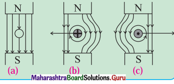
If a wire without any current is kept in a magnetic field, then it experiences no force as shown in figure (a). But when the wire is carrying a current into the plane of the paper in the magnetic field, a force will be exerted on the wire towards the left as shown in the figure (b). The field will be strengthened on the right side of the wire where the lines of force are in the same direction as that of the magnetic field and weakened on the left side where the field lines are in opposite direction to that of the applied magnetic field. For a wire carrying a current out of the plane of the paper, the force will act to the right as shown in figure (c).
Answer:
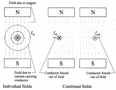
Force on a current-carrying conductor in a magnetic field, \(\vec{F}=I \vec{L} \times \vec{B}\) (Refer unit 10.5). The field due to acurrent-carrying straight conductor is given by right- hand grip rule. As shown in the figure below, the combined field due to a permanent magnet and a current-carrying conductor force the conductor out of the field. The field is strengthened where the two fields are in the same direction and add constructively while the field is weakened where the two fields are opposite in direction.
![]()
Use your brain power (Textbook Page No. 282)
Question 1.
It can be shown that the mutual potential energy of two circuits is W = MI1I2. Therefore, the mutual inductance (M) may also be defined as the mutual potential energy (W) of two circuits corresponding to unit current flowing in each circuit.
M = \(\frac{W}{I_{1} I_{2}}\)
M = W[I1 = I2 = 1]
Answer:
Mutual inductance of two magnetically linked coils equals the potential energy for unit currents in the coils.
1 H = 1 T∙m2/A (= 1 V∙s/A = 1 Ω ∙ s = 1 J/A2)
Use your brain power (Textbook Page No. 284)
Question 1.
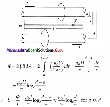
Prove that the inductance of parallel wires of length l in the same circuit is given by L = \(\left(\frac{\mu_{0} l}{\pi}\right)\) ln (d / a), where a is the radius of wire and d is separation between wire axes.
Answer:
If l is the current in each wire, from Ampe’re’s law the magnitude of the magnetic field outside each wire is
B = \(\frac{\mu_{0} I}{2 \pi r}\)
By right hand grip rule, the direction of the magnetic field due to both the wires are in the same direction at the point shown. Hence, by the symmetry of the setup, the total magnetic flux through an area dA = l dr shown is two times that due to one wire.
Do you know (Textbook Page No. 285)
Question 1.
The flux rule is the terminology that Feynman used to refer to the law relating magnetic flux to emf. (RP Feynman, Feynman Lectures on Physics, Vol II)
Answer:
Modern applications of Faraday’s law of induction :
- Electric generators and motors
- Dynamos in vehicles
- Transformers
- Induction furnaces (industrial), induction cooking stoves (domestic)
- Radio communication
- Magnetic flow meters and energy meters
- Metal detectors at security checks
- Magnetic hard disk and tape, storage and retrieval
- Graphics tablets
- ATM Credit/debit cards, ATM and point-of-sale (POS) machines
- Pacemakers
Faraday’s second law of electromagnetic induction is referred to by some as the “flux rule”.
12th Std Physics Questions And Answers:
- Current Electricity Class 12 Physics Questions And Answers
- Magnetic Fields due to Electric Current Class 12 Physics Questions And Answers
- Magnetic Materials Class 12 Physics Questions And Answers
- Electromagnetic Induction Class 12 Physics Questions And Answers
- AC Circuits Class 12 Physics Questions And Answers
- Dual Nature of Radiation and Matter Class 12 Physics Questions And Answers
- Structure of Atoms and Nuclei Class 12 Physics Questions And Answers
- Semiconductor Devices Class 12 Physics Questions And Answers
