Balbharti Maharashtra State Board 12th Physics Important Questions Chapter 13 AC Circuits Important Questions and Answers.
Maharashtra State Board 12th Physics Important Questions Chapter 13 AC Circuits
Question 1.
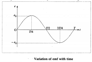
Write an expression for an alternating emf that varies sinusoidally with time. Show graphically variation of emf with time.
Answer:
An alternating emf that varies sinusoidally with time is given by e = e0 sin ωt, where e0 is the maximum value of the emf, called the peak value, and co is the angular frequency of the emf.
ω = 2πf = \(\frac{2 \pi}{T}\), where f is the frequency of the emf, expressed in Hz, and T is the periodic time of the emf, expressed in second.
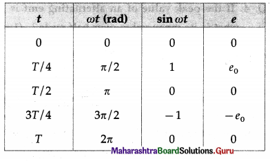
Using these data, we can plot e versus t
Question 2.
An alternating emf is given by e = 2.20 sin ωt (in volt). What will be its value at time t = \(\frac{T}{12}\)?
Answer:
e = 220 sin[latex]\frac{2 \pi}{T}\left(\frac{T}{12}\right)[/latex]= 220 sin(\(\frac{\pi}{6}\))
= 220 \(\left(\frac{1}{2}\right)\) = 110 v.
![]()
Question 3.
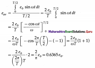
What is the average or mean value of an alternating emf? Obtain the expression for it. (2 marks)
Answer:
The average or mean value of an alternating emf is defined as its average value over half cycle (because the average value over one cycle is zero) and is given as
Question 4.
If the peak value of an alternating emf is 10 V, what is its mean value over half cycle?
Answer:
eav = 0.6365 e0 = 0.6365(10) = 6.365 V
Note: In general, when e = e0 sin ωt, the correspond ing current is j = i sin (ωt + α), where α is the phase difference between emf e and current j. ¿z may be positive or negative or zero.
i0 is the peak value of the current and iav (over half cycle)
= \(\frac{2}{\pi}\) i0 = 0.6365 i0].
Question 5.
What is the rms value of an alternating current? Find the relation between the rms value and peak value of an alternating current that varies sinusoidaily with time.
Answer:
The root mean square (rms) value of an alternating current i is, by definition,
irms = \(\left[\frac{\int_{0}^{I} i^{2} d t}{T}\right]^{\frac{1}{2}}\), where T is the periodic time, i.e., time for one cycle.
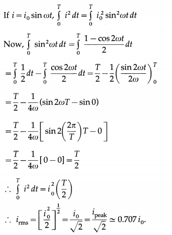
[Note: irms is also called the effective value or virtual value of the alternating current. In one cycle, the heat produced in a resistor by i = i0 sin ωt is the same as that produced by a direct current (dc) equal to irms]
![]()
Question 6.
What is the relation between i,, (over half cycle) and irms?
Answer:
iav (over half cycle) = \(\frac{2}{\pi}\) i0, and irms = \(\frac{i_{0}}{\sqrt{2}}\)
∴ iav (over half cycle) = \(\left(\frac{2}{\pi}\right)\left(\sqrt{2} i_{\mathrm{rms}}\right)=\frac{2 \sqrt{2}}{\pi} i_{\mathrm{rms}}\)
Question 7.
If irms = 3.142 A, what is iav (over half cycle)?
Answer:
iav (over half cycle) = \(\frac{2 \sqrt{2}}{\pi}\) irms
= \(\frac{(2)(1.414)}{3.142}\)(3.142) = 2.828 A
[Note: iav (over half cycle) < irms]
Question 8.
For e = e0 sin ωt, what is
(i) eav (over half cycle)
(ii) rrms
Answer:
For e = e0 sin ωt, eav (over half cycle) = \(\frac{2}{\pi}\) e0 and erms = \(\frac{e_{0}}{\sqrt{2}}\)
9. Solve the following:
Question 1.
An alternating emf is given by e = 220 sin 314.2 t (in volt). Find its
(i) peak value
(ii) rms value
(iii) average value over half cycle
(iv) frequency
(iv) period
(vi) value at \(\frac{T}{4}\) .
Solution:
Data: e = 220 sin314.2t (in volt), t = \(\frac{T}{4}\)
(i) Comparing the given equation with e = e0 sin ωt, we get, peak value, e0 = 220V.
(ii) erms = e0/\(\sqrt{2}\) = 155.6 V
(iii) eav (over half cycle) = \(\frac{2}{\pi}\)e0 = \(\frac{2(220)}{3.142}\) = 140V
(iv) ω = 2πf= 314.2 ∴ The frequency,
f = \(\frac{\omega}{2 \pi}=\frac{314.2}{2(3.142)}\) = 50 Hz
(v) The period, T = \(=\frac{1}{f}=\frac{1}{50}\) = 0.02 same
(vi) e = 220 sin(\(\frac{2 \pi}{T} \cdot \frac{T}{4}\)) = 220 sin \(\frac{\pi}{2}\) = 220 v
Question 2.
The peak value of AC through a resistor of 10 Ω is 10 mA. What is the voltage across the resistor at time
Solution:
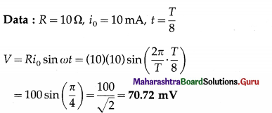
This is the required voltage.
Question 3.
The peak value of AC through a resistor of 100 Ω is 2A If the frequency of AC is 50Hz, find the heat produced in the resistor in one cycle.
Solution:
Data: R = 100 Ω, i0 = 2A, f = 50 Hz
H = \(\frac{R i_{0}^{2}}{2 f}=\frac{100(2)^{2}}{2(50)}\) = 4 J
This is the required quantity.
![]()
Question 10.
What is a phasor?
Answer:
A phasor is a rotating vector that represents a quantity varying sinusoidally with time.
Question 11.
What is a phasor diagram ? Illustrate it with an example.
Answer:
A diagram that represents a phasor is called phasor diagram. Consider an alternating emf e = e0 sin ωt. The phasor representing it is inclined to the horizontal axis at an angle cot and rotates in an anticlockwise direction as shown in below figure.
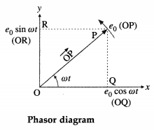
The length (OP) of the arrow \(\overrightarrow{\mathrm{OP}}\) represents the peak value (maximum value), e0, of the emf.
For e = e0 sin ωt, the projection of \(\overrightarrow{\mathrm{OP}}\) on the y-axis gives the instantaneous value of the emf.
In above figure, OR = e0 sin ωt.
For e = 0 sin ωt, the projection of \(\overrightarrow{\mathrm{OP}}\) on the x-axis gives the instantaneous value of the emf.
In above figure, OQ = e0 sin ωt.
Phasor diagrams are useful in adding harmonically varying quantities.
Question 12.
An alternating emf e = e0 sin ωt is applied to a resistor of resistance R. Write the expression for the current through the resistor. Show the variation of emf and current with ωt. Draw a phasor diagram to show emf and current.
Answer:
Below figure shows an alternating emf e = e0 sin ωt applied to a resistor of resistance R.
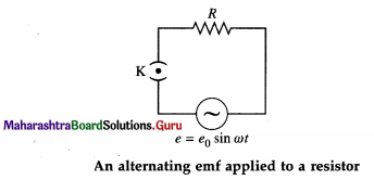
e0 is the peak value and co is the angular frequency of the emf. The instantaneous current through the resistor is i = i0 sin ωt, where i0 is the peak value of the current.
Here, i and e are always in phase.
For ωt = 0, sin ωt = 0,e = 0,i = 0;
for ωt = π/2, sin ωt = 1, e = e0, i = i0;
for ωt = π, sin ωt = 0, e = 0, i = 0;
for ωt = 3π/2, sin ωt = -1, e= – e0, i= -i0;
for ωt = 2π, sin ωt = 0, e = 0, i = 0.
Below figure shows variation of e and i with cot.
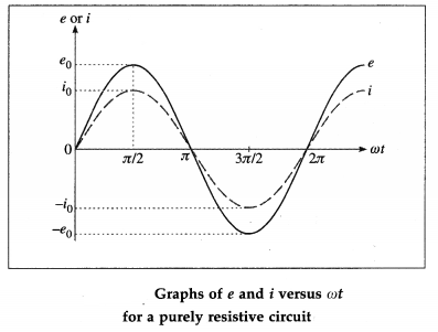
Below figure shows phasors of e and i
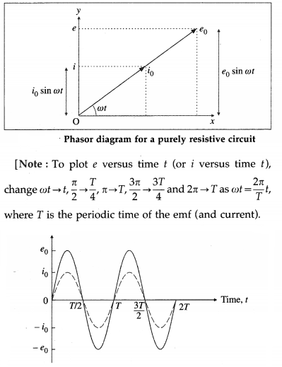
Variation of e and i with time t for a purely resistive AC circuit
![]()
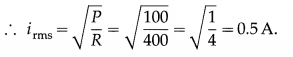
Question 13.
If the peak value of the alternating emf applied to a resistor of 100Ω is 100 V, what is the rms current through the resistor?
Answer:
The rms current through the resistor,
irms = \(\frac{i_{0}}{\sqrt{2}}=\frac{e_{0}}{R \sqrt{2}}=\frac{100}{100 \sqrt{2}}\) = 0.7071 A
Question 14.
An alternating emf e = e0 sin ωt is applied to a pure inductor of inductance L. Show variation of the emf and current with ωt.
Answer:
Here, e = e0 sin ωt and i = i0 sin (ωt – π/2), where i0 = e0/ωL.
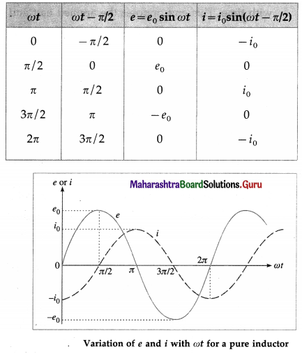
[Note : A pure inductor ≡ an ideal inductor.]
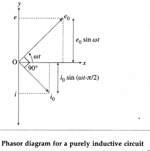
Question 15.
Draw a Phasor diagram showing e and i in the case of a purely inductive circuit.
Answer:
In this case, e = e0 sin ωt and i = i0 sin (ωt – \(\frac{\pi}{2}\)),
where i0 = \(\frac{e_{0}}{\omega L}\) and L is the inductance of the inductor. In this case, the current j lags behind the emf e by a phase angle of \(\frac{\pi}{2}\) rad.
Question 16.
Explain the term inductive reactance. Show graphically variation of inductive reactance with the frequency of the applied alternating emf.
Answer:
When an alternating emf e = e0 sin ωt is applied to a pure inductor of inductance L, the current in the
circuit is i = i0 sin (ωt – \(\frac{\pi}{2}\)), where i0 = \(\frac{\pi}{2}\), where i0 = \(\frac{e_{0}}{\omega L}\) In the case of a pure resistor of resistance R, i = i0 sin ωt for e = e0 sin ωt, and i0 = \(\frac{e_{0}}{R}\)
Comparison of Eqs. i0 = \(\frac{e_{0}}{\omega L}\) and i0 = \(\frac{e_{0}}{R}\) shows that ωL is the resistance offered by the inductor to the applied alternating emf. It is called the reactance. It increases linearly with the frequency because ωL = 2πfL. This is illustrated in the following figure. ωL is denoted by XL.
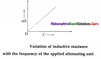
[Note : Reactance has the same dimensions and unit as resistance.]
Question 17.
What is the reactance of a pure inductor with inductance 10H if the frequency of the applied alternating emf is 50 Hz?
Answer:
The reactance of the inductor,
XL = ωL = 2πfL = 2(3.142)(50)(10) = 3142 Ω
[Note : In a DC circuit, f = 0 ∴ XL = 2πfL = 0.]
![]()
Question 18.
How does a pure inductor behave when the frequency of the applied alternating emf is
(i) very high
(ii) very low?
Answer:
Inductive reactance = 2πfL.
(i) If the frequency (f) of the applied emf is very high, the inductive reactance (for reasonable value of inductance L) will be very high. Hence, the current through the inductor will be very low (for reasonable value of peak emf). Hence, it will practically block AC.
(ii) For very low f, 2πfL is low and hence the inductor will behave as a good conductor.
Question 19.
The capacitance of an ideal capacitor is 2 μF. What is its reactance if the frequency of the applied alternating emf is 1000 Hz?
Answer:
The reactance of the capacitor =
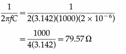
Question 20.
How does a pure (an ideal) capacitor behave when the frequency of the applied alternating emf is very low?
Answer:
Capacitive reactance = \(\frac{1}{2 \pi f C}\)
If the frequency (f) of the applied emf is very low, the capacitive reactance (for reasonable value of capacitance C) will be very high and hence the current through the circuit will be very low (for reasonable value of peak emf).
Question 21.
What will be the current through an ideal capacitor if it is connected across a 2 V battery ?
Answer:
In a DC circuit, the frequency (f) of the applied emf is zero.
∴ Capacitive reactance, \(\frac{1}{2 \pi f C}\) = ∞
∴ The current through the capacitor will be zero.
(Note : The capacitor blocks DC and acts as an open circuit while it passes AC of high frequency.]
![]()
Question 22.
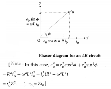
An alternating emf is applied to an LR circuit. Assuming the expression for the current, obtain the expressions for the applied emf and the effective resistance of the circuit. Assume the inductor and resistor to be ideal. Draw the phasor diagram showing the emf and current.
Answer:
Below figure shows a source of alternating emf (e), key K, ideal inductor of inductance L and ideal resistor of resistance R connected to form a closed series circuit. Ignoring the resistance of the source andthekey,wehave,e = Ri + L\(\frac{d i}{d t}\) …………… (1)
where Ri is the potential difference across R and L\(\frac{d i}{d t}\) is the potential difference across L.
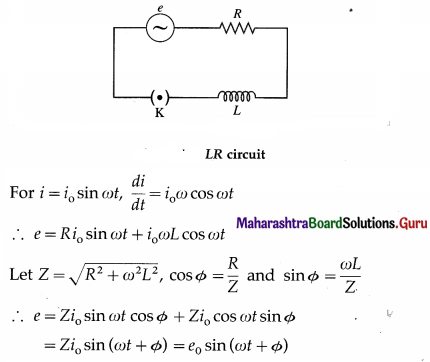
where e0 = Zi0 is the peak value of the applied emf.
Z = \(\frac{e_{0}}{i_{0}}=\sqrt{R^{2}+\omega^{2} L^{2}}\) is the effective resistance of the circuit. It is called the impedance. Here, the emf leads the current by phase angle Φ.
Question 23.
(a) What is the impedance of an LR circuit if R = 40 Ω and XL = 30 Ω ?
(b) What is the peak current if the peak emf is 10 V, R = 0 and XL = 30 Ω?
Ans.
(a) The impedance, Z = \(\sqrt{R^{2}+X_{\mathrm{L}}^{2}}\)
= \(\sqrt{1600+900}=\sqrt{2500}\) = 50 Ω.
(b) i0 = \(\frac{e_{0}}{X_{\mathrm{L}}}=\frac{10}{30}=\frac{1}{3}\) A = 0.3333 A.
Question 24.
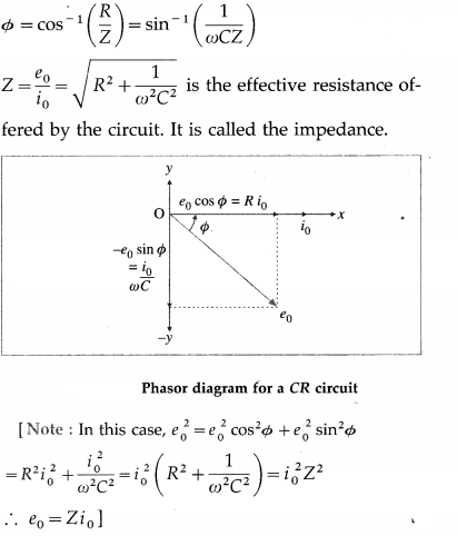
An alternating emf is applied to a CR circuit. Obtain an expression for the phase difference between the emf and the current. Also obtain the expression for the effective resistance of the cir-cuit. Assume the capacitor and resistor to be ideal. Draw the phasor diagram showing the emf and current.
Answer:
Below figure shows a source of alternating emf (e), key K, ideal capacitor of capacitance C and ideal resistor of resistance R to form a closed series circuit. Ignoring the resistance of the source and the key, we have,
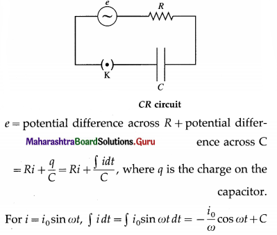
where C is the time independent constant of integration which must be zero as j oscillates about zero when e oscillates about zero.
∴ e = R i0 sin ωt – \(\frac{i_{0}}{\omega C}\) cos ωt
Let Z = \(\sqrt{R^{2}+\frac{1}{\omega^{2} C^{2}}}\), R = Z cos and \(\frac{1}{\omega C}\) = Z sin Φ
∴ e = i0Z (cos Φ sin ωt – sin Φ cos ωt)
= Zi0 (sin ωt cos Φ – cos ωt sin Φ)
= Zi0 sin (ωt – Φ) = e0 sin (ωt – Φ), where e0 = Zi0 is the peak emf. Here, the emf lags behind the current by phase angle Φ.
Question 25.
(a) What is the impedance of a CR circuit if R = 30 Ω and XC = 40 Ω?
(b) What is the peak current if the peak emf is 10 V, R = 0 and XC = 40 Ω ?
Ans.
(a) The impedance, Z = \(\sqrt{R^{2}+X_{\mathrm{C}}^{2}}=\sqrt{900+1600}\)
= \(\sqrt{2500}\) = 50
(b) The peak current i0 = \(\frac{e_{0}}{X_{C}}=\frac{10}{40}\) = 0.25 A.
![]()
Question 26.
What is meant by the term impedance? State the formula for it in the case of an LCR series circuit.
Answer:
In an AC circuit containing resistance and inductance and / or capacitance, the effective resistance offered by the circuit to the flow of current is called impedance. It is denoted by Z.
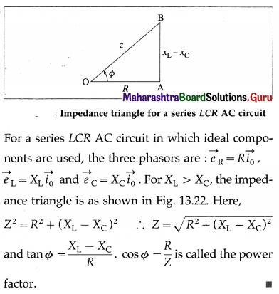
For an LCR series circuit,
Z = \(\sqrt{R^{2}+\left(\omega L-\frac{1}{\omega C}\right)^{2}}\) where
ω = 2πf is the angular frequency and f is the frequency of AC.
[Note: Here, in the absence of a capacitor.
Z = \(\sqrt{R^{2}+\omega^{2} L^{2}}\), and in the absence of an inductor,
Z = \(\sqrt{R^{2}+\frac{1}{\omega^{2} C^{2}}}\)].
Question 27.
Draw the impedance triangle for a series LCR AC circuit and write the expressions for the im-pedance and the phase difference between the emf and the current.
Answer:
28. Solve the following :
Question 1.
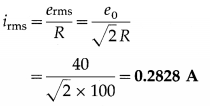
An alternating emf e = 40 sin (120 πt) (in volt) is applied across a 100 Ω resistor. Calculate the rms current through the resistor and the frequency of the applied emf.
Solution:
Data : e = 40 sin (120 πt) V, R = 100 Ω
The equation of a sinusoidally alternating emf is e = e0 sin ωt
where e0 is the peak value of the emf.
Comparing the given expression with this, we get, e0 = 40 V
∴ The rms current,
Comparing e = 40 sin (120 πt) with
e = e0 sin ωt, we get,
ω = 2πf= 120 π
∴ f = 60 Hz
This is the frequency of the applied emf.
Question 2.
In problem (1) above, what is the period of the AC?
Solution:
The period of the AC,
T = \(\frac{1}{f}=\frac{1}{60}\) s ≈ 0.01667 s
Question 3.
An alternating emf of frequency 50 Hz is applied a series combination of an inductor (L = 2 H) and a resistor (R = 100 Ω). What is the impedance of the circuit?
Solution:
Data : f = 50 Hz, L = 0.2 H, R = 100 Ω
The inductive reactance, XL = 2πfL
= 2(3.142)(50)(0.2) = 62.84 Ω
The impedance of the circuit, Z = \(\sqrt{R^{2}+X_{\mathrm{L}}^{2}}\)
= \(\sqrt{(100)^{2}+(62.84)^{2}}=\sqrt{10000+3949}=\sqrt{13949}\)
= 118.1 Ω
![]()
Question 4.
An alternating emf is applied to a series combination of an inductor and a resistor (R = 100 Ω). If the impedance of the circuit is 100\(\sqrt {2}\) Ω, what is the phase difference between the emf and the current?
Solution:
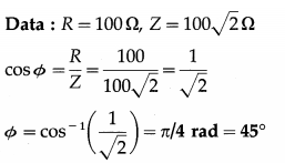
This is the phase difference between the emf and the current.
Question 5.
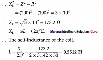
When 100 V dc is applied across a coil, a current of 1 A flows through it. When 100 V ac of frequency 50 Hz is applied to the same coil, only 0.5 A current flows through it. Calculate the resistance, impedance and self-inductance of the coil.
Solution:
Data : Vdc = 100 V, Idc = 1 A, Vrms = 100 V,
f = 50 Hz, Irms = 0.5 A
(i) The resistance of the coil,
R = \(\frac{V_{\mathrm{dc}}}{I_{\mathrm{dc}}}=\frac{100}{1}\) = 100 Ω
(ii) The impedance of the coil,
Z = \(\frac{V_{\mathrm{rms}}}{I_{\mathrm{rms}}}=\frac{100}{0.5}\) = 200 Ω
Z2 = R2 + X2L
Question 6.
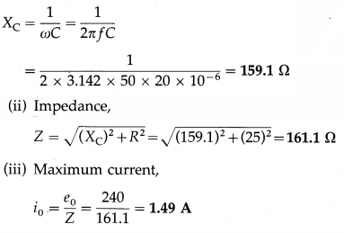
A 20 µF capacitor is connected in series with a 25 Ω resistor and a source of alternating emf, 240 V (peak)/50 Hz. Calculate the capacitive reactance, circuit impedance and the maximum current in the circuit.
Solution:
Data : C = 20 µF = 20 × 10-6 F, k = 25 Ω, e0 = 240 V, f = 50 Hz
(i) Capacitive reactance,
Question 7.
A 25 µF capacitor, 0.1 H inductor and 25 Ω resistor are connected in series with an ac source of emf e = 220 sin 314t volt. What is the expression for the instantaneous value of the current?
Solution:
Data : C = 25 µF = 25 × 10-6 F, L = 0.1 H,
R = 25 Ω, e = 220 sin 314t volt
The equation of a sinusoidally alternating emf is e = e0 sin ωt, where e0 is the peak emf. Comparing the given expression with this, we get,
e0 = 220 V, ω = 314 rad/s
∴ Inductive reactance,
XL = ωL = 314 × 0.1 = 31.4 Ω and capacitive reactance,
XC = \(\frac{1}{\omega C}=\frac{1}{314 \times 25 \times 10^{-6}}\) = 127.4 Ω
∴ The reactance of the circuit,
|XL – XC| = 96 Ω (capacitive, ∵ XC > XL)
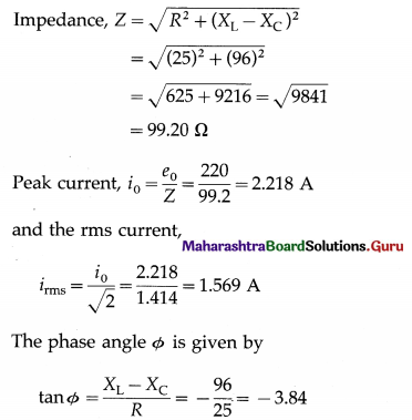
∴ Φ = – 75°24′
i. e., the applied emf lags behind the current by 75°24′.
The instantaneous value of the current is i = i0 sin (ωt + Φ)
∴ i = 1.569 sin (314 f + 75°24′) ampere
![]()
Question 8.
An alternating emf of peak value 110 V and frequency 50 Hz is connected across an LCR series circuit with R = 100 Ω, L = 10 mH and C = 25 µF. Calculate the inductive reactance, capacitive reactance and impedance of the circuit.
Solution:
Data : e0 = 110 V, f = 50 Hz, R = 100 Ω,
L = 10 mH = 10 × 10-3 H, C = 25 µF = 25 × 10-6 F
(i) Inductive reactance,
XL = ωL = 2πfL
= 2 × 3.142 × 50 × 10 × 10-3 = 3.142 Ω
(ii) Capacitive reactance,
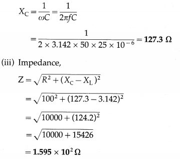
Question 29.
An alternating emf with rms value 100 V is applied to a pure resistor of resistance 100 Ω. What is the power consumed over one cycle ?
Answer:
The power consumed over one cycle = erms irms
= erms \(\left(\frac{e_{\mathrm{rms}}}{R}\right)\) = (100) \(\left(\frac{100}{100}\right)\) = 100 W.
Question 30.
An alternating emf is applied to a pure resistor of 400 Ω. If the power consumed over one cycle is 100 W, what is the rms current through the resistor?
Answer:
Pav = R (irms)2
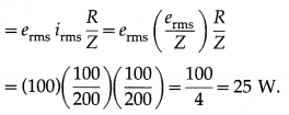
Question 31.
An alternating emf with erms = 100 V is applied to a series LR circuit with R = 100 Ω and Z = 200 Ω What is the average power consumed over one cycle?
Answer:
The average power consumed over one cycle
![]()
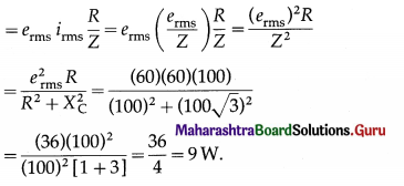
Question 32.
An alternating emf with erms = 60 V is applied to a series CR circuit with R = 100 \(\sqrt {3}\) Ω and capacitive reactance 100 V 3Q. What is the average power consumed over one cycle ?
Answer:
The average power consumed over one cycle
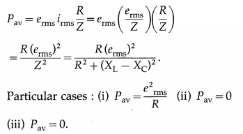
Question 33.
State the expression for the average power consumed over one cycle in the case of a series LCR AC circuit. What happens if the circuit is purely
(i) resistive
(ii) inductive
(iii) capacitive?
Answer:
Average power consumed over one cycle in the case of a series LCR AC circuit,
Question 34.
In the case of a series LCR AC circuit, what is the power factor if
(i) the resistance is far greater than the reactance
(ii) the resistance is far less than the reactance?
Answer:
Power factor, cos Φ = \(\frac{R}{\sqrt{R^{2}+\left(X_{\mathrm{L}}-X_{\mathrm{C}}\right)^{2}}}\)
(i) For R >> (XL – XC), cos Φ ≅ 1
(ii) For R >> (XL – Xe), cos Φ ≅ zero.
35. Solve the following.
Question 1.
An alternating emf e = 200 sin ωt (in volt) is connected to a 1000 Ω resistor. Calculate the rms current through the resistor and the average power dissipated in it in one cycle.
Solution:
Data: e = 200 sin ωt V, R = 1000 Ω
The equation of a sinusoidally alternating emf is e = e0 sin ωt, where e0 is the peak value of the emf.
Comparing the given expression with this, we get
∴ Peak current, i0 = \(\frac{e_{0}}{R}=\frac{200}{1000}\) = 0.2 A
∴ rms current, irms = \(\frac{i_{0}}{\sqrt{2}}=\frac{0.2}{\sqrt{2}}\) = 0.1414 A
The average power dissipated in the resistor in one cycle,
Pav = erms irms = \(\frac{e_{0} i_{0}}{2}=\frac{200 \times 0.2}{2}\) = 20 W
![]()
Question 2.
A circuit has a resistance and a reactance, each equal to 100 Ω Find its power factor. If the rms value of the applied voltage is 200 V, what is the average power consumed by the circuit?
Solution:
Data : R = 100 Ω, X = 100 Ω, Vrms = 200 V
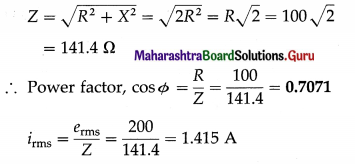
∴ The average power, P = erms irms cos Φ
= 200 × 1.415 × 0.7071 = 200 W
Question 3.
A dc ammeter and an ac hot-wire ammeter are connected to a circuit in series. When a direct current is passed through the circuit, the dc ammeter shows 6A. When a pure alternating current is passed, the ac ammeter shows 8 A. What will be the reading of each ammeter if the direct and alternating currents pass simultaneously through the circuit?
Solution:
Data: idc = 6 A, irms(ac) = 8A
A dc ammeter measures the average value of a current passing through it. Since the average value of an alternating current over one cycle is zero, when the direct and alternating currents are siniultaneously passed, the dc ammeter will read 6 A which is the dc part.
An ac hot-wire ammeter measures the effective value of a current using the heating effect of an electric current. When the direct and alternating currents are simultaneously passed through the ac ammeter, the average power dissipated is
Pav = i2dcR + i2rms = i2eff R
where R is the resistance of the heating element of the ac ammeter.
∴ ieff = \(\sqrt{i_{\mathrm{dc}}^{2}+i_{\mathrm{rms}}^{2}}\)
= \(\sqrt{(6)^{2}+(8)^{2}}\) = 10 A
Thus, the ac ammeter will read 10 A.
Question 4.
An alternating emf e = 100 sin [2π(1000) t] (in volt) is applied to a series LCR circuit with resistance 300 Ω, inductance 0.1 H and capacitance 1 µF. Find the power factor and the average power consumed over one cycle.
Solution:
Data: e = 100 sin[2π (1000)t] (in volt), R = 300 Ω L = 0.1H, C = 1 µF = 1 × 10⁻⁶ F
Comparing e = e0 sin 2πft with the given equation,
we get e0 = 100 V, f = 1000 Hz
∴ XL = 2πfL = 2(3.142)(1000)(0.1) = 628.4 Ω
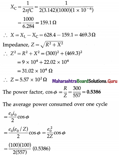
= 4.835 W
Question 5.
An ac circuit with a 10 Ω resistor, 0.1 H inductor and 50 µF capacitor is connected across a 200 V/50 Hz supply. Compute
(i) the power factor
(ii) the average power dissipated in the circuit.
Solution:
Data : R = 10 Ω, L = 0.1 H, erms = 200 V, C = 50 µF = 50 × 10-6 F, f = 50 Hz
(i) XL = ωL = (2πf)L
= 2 × 3.142 × 50 × 0.1
= 31.42 Ω
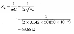
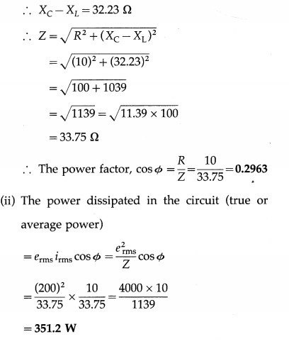
[Note: An alternating emf is usually specified by giving its rms value.]
![]()
Question 36.
How are oscillations produced using an inductor and a capacitor?
Answer:
Consider a charged capacitor of capacitance C, with an initial charge q0, connected to an ideal inductor of inductance L through a key K. We assume that the circuit does not include any resistance or a source of emf. At first, the energy stored in the electric field in the dielectric medium between the plates of the capacitor is UE = \(\frac{1}{2} \frac{q_{o}^{2}}{C^{\prime}}\), while the energy stored in the magnetic field in the inductor is zero.
When the key is closed, the capacitor begins to discharge through the inductor and there is a clockwise current in the circuit, as shown in below figure (a). Let q and i are the instantaneous values of charge on the capacitor and current in the circuit, respectively.
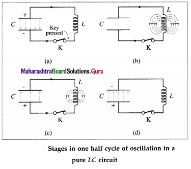
As q decreases, i increases : i = – dq/dt. Thus, the energy UB = \(\frac{1}{2}\) Li2 stored in the magnetic field of the inductor increases from zero. Since the circuit is free of resistance, energy is not dissipated in the form of heat, so that the decrease in the energy stored in the capacitor appears as the increase in energy stored in the inductor. As the current reaches its maximum value i(y the capacitor is fully discharged and all the energy is stored in the inductor, from figure (b).
Although q = 0 at this instant, dq/dt is nonzero. The current in the inductor then continues to transfer charge from the top plate of the capacitor to its bottom plate, as in from figure (c). The electric field in the capacitor builds up again, but now in the opposite sense, as energy flows back into it from the inductor. Eventually, all the energy of the magnetic field of the inductor is transferred back into the electric field of the capacitor, which is now fully charged, from figure (d).
The capacitor then begins to discharge with an anticlockwise current until the energy is completely back with the inductor. The magnetic field in the inductor is in the opposite sense and becomes maximum when the current reaches its maximum minimum value – i0. Subsequently, the current in the inductor charges the capacitor once again until the capacitor is fully charged and back to its original condition.
In the absence of an energy dissipative resistance (ideal condition), this cycle continues indefinitely. When the magnitude of the current is maximum, the energy is stored completely in the magnetic field. When the energy is stored entirely in the electric field, the current is zero. The current varies sinusoidally with time between i0 and – i0. The frequency of this electrical oscillation in the LC circuit is determined by the values of L and C.
[Notes : (1) Electrical oscillations in an LC circuit are analogous to the oscillations of an ideal mechanical oscillator. An LC circuit with resistance is analogous to a damped mechanical oscillator, while one with a source of alternating emf is analogous to a forced mechanical oscillator. (2) With suitable choices of L and C, it is possible to obtain frequencies ranging from 10 Hz to 10 GHz. (3) In practice, LC oscillations are damped because an inductor has some resistance (R) and hence Joule heat (izRt) is developed in it. The amplitude of oscillations goes on decreasing with time and becomes zero eventually. Also, part of energy stored in the inductor and capacitor is radiated in the form of electromagnetic waves. Working of radio and TV transmitters is based on such radiation.]
Question 37.
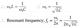
Explain electrical resonance in an LCR series circuit. Deduce the expression for the resonant frequency of the circuit.
Answer:
Suppose a sinusoidally alternating emf e, of peak value e0 and frequency f, is applied to a circuit containing an inductor of inductance L, a resistor of resistance R and a capacitor of capacitance C, all in series, from figure (a) The inductive reactance, XL, and the capacitive reactance, XC, are
XL = ωL and XC = \(\frac{1}{\omega C}\)
where ω = 2πf.
The rms values irms and erms of current and emf are proportional to one another.
irms = \(\frac{e_{\mathrm{rms}}}{\mathrm{Z}}\)
where Z = \(\sqrt{R^{2}+\left(X_{\mathrm{L}}-X_{\mathrm{C}}\right)^{2}}\) = the impedance of the circuit.
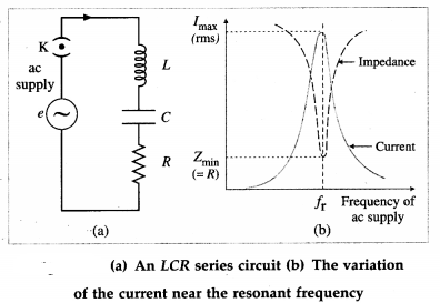
The impedance Z drops to a minimum at the frequency fr for which the inductive and capacitive reactances are equal (and opposite, in a phasor diagram); i.e., when
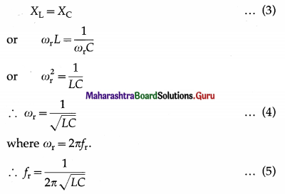
At this frequency, Z = R and the phase angle Φ = 0, i.e., the combination behaves like a pure
resistance, and the current and emf are in phase. If R is small, the loss is small. Then, the current may be very large. At any other frequency, the impedance is greater than R. If a mixture of frequencies is applied to the circuit, the current only builds up to a large value for frequencies near the one to which the circuit is ‘tuned’, as given by Eq. (5). The resonance curve, from figure (b), shows the variation of the rms current with frequency. This is an example of electrical resonance. Equations (3) or (4) give the resonance condition and fris called the resonant frequency of the LCR series circuit.
At the resonant frequency, the potential differences across the capacitor and inductor are equal in magnitude but in exact antiphase; the current is in quadrature, i.e., 900 out of phase with them. The energy stored in the electric field of the capacitor changes periodically as the square of the potential difference across it; while the energy stored in the magnetic field of the inductor changes periodically as the square of the current. At moments when the potential difference across the capacitor is a maximum and the current through the inductor zero, there is then a maximum of energy stored in the electric field of the capacitor. At moments the potential difference across the capacitor is zero and the current through the inductor a maximum, there is then a maximum of energy stored in the magnetic field of the inductor.
At resonance, the total energy stored in the L-C system is constant, and is simply passed back and forth between the electric and magnetic fields. When the resonant current is first building up, this energy is drawn from the ac supply. After that, the supply only needs to make up the energy lost as heat in the resistor.
Question 38.
State the characteristics of a series LCR AC resonance circuit.
Answer:
Characteristics of a series LCR AC resonance circuit:
- Resonance occurs when inductive reactance (XL = 2πfL) equals capacitive reactance j (XC = \(\frac{1}{2 \pi f C}\)). Resonant frequency, fr = \(\frac{1}{2 \pi \sqrt{L C}}\).
- Impedance is minimum and the circuit is purely resistive.
- Current is maximum.
- Frequencies, other than the resonant frequency (fr) are rejected. Only fr is accepted. Hence, it is called the acceptor circuit.
![]()
Question 39.
In LCR series circuit, what is the condition for current resonance ?
Answer:
In LCR series circuit, the condition for current resonance is ωL = \(\frac{1}{\omega C}\) or f = \(\frac{1}{2 \pi \sqrt{L C}},\), where L is the inductance, C is the capacitance and / is the frequency of the applied alternating emf.
Question 40.
In LCR series circuit, what is the
(i) reactance and
(ii) impedance at current resonance?
Answer:
In LCR series circuit, at current resonance,
- reactance is zero and
- impedance equals resistance R.
Question 41.
A series LCR circuit has resistance 5 Ω and reactance, for a certain frequency, is 10\(\sqrt {2}\) Ω, what is the impedance of the circuit?
Answer:
Z = \(\sqrt{R^{2}+\left(X_{\mathrm{L}}-X_{\mathrm{C}}\right)^{2}}=\sqrt{(5)^{2}+(10 \sqrt{2})^{2}}\)
= \(\sqrt{25+200}=\sqrt{225}\) = 15 Ω is the impedance of the circuit.
Question 42.
In LCR series circuit, what is the
(i) power factor and
(ii) phase difference between the emf and current, at resonance.
Answer:
At resonance,
- the power factor is 1 and
- the phase difference between the emf and current is zero.
Question 43.
What is an acceptor circuit ? State its use.
Answer:
An acceptor circuit is a series LCR resonant circuit used in communications and broadcasting to selec-tively pass a current for a signal of only the desired frequency.
The resonance curve of a series LCR resonant circuit with a small resistance exhibits a very sharp peak at a certain frequency called the resonant frequency fr. For an alternating signal of this frequency, the impedance of the circuit is minimum, equal to R, and the current is maximum. That is, the circuit has a selective property as it prefers to pass a signal of frequency fr and reject those of other frequencies.
Use : An acceptor circuit is used in a radio or television receiver to accept the signal of a desired broadcasting station or channel from all the signals that arrive concurrently at its antenna. Tuning a receiver means adjusting the acceptor circuit to be resonant at a desired frequency.
![]()
Question 44.
Explain electrical resonance in an LC parallel circuit. Deduce the expression for the resonant frequency of the circuit.
Answer:
Consider a capacitor of capacitance C, and an inductor of large self-inductance L and negligible resistance, connected in parallel across a source of sinusoidally alternating emf from below figure. Let the instantaneous value of the applied emf be
e = e0 sin ωt
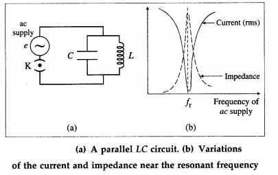
Let iL and iC be the instantaneous currents through the inductor and capacitor respectively.
As the current in the inductor lags behind the emf in phase by π/2 radian,
iL = \(\frac{e_{0}}{X_{\mathrm{L}}} \sin \left(\omega t-\frac{\pi}{2}\right)=-\frac{e_{0}}{X_{\mathrm{L}}} \cos \omega t\)
where XL is the inductive reactance.
As the current in the capacitor leads the emf by a phase angle of π/2 radian,
iC = \(\frac{e_{0}}{X_{C}}\) sin (ωt + π/2) = \(\frac{e_{0}}{X_{C}}\) cos ωt
where XC is the capacitive reactance.
The instantaneous current drawn from the source is
i = iL + iC = e0 \(\left(\frac{1}{X_{\mathrm{C}}}-\frac{1}{X_{\mathrm{L}}}\right)\) cos ωt
If XL = XC, i = 0. Thus, no current is drawn from the source if XL = XC. In such a case, alternating current goes on circulating in the LC loop, though no current is supplied by the source. This condition is called parallel resonance and the frequency of ac at which it occurs is called the resonant frequency (fr).
The condition for resonance is
XL = XC
In practice, every inductor possesses some resistance and hence even at resonance, some current is drawn from the source. Also, the resonant frequency is different from that for zero resistence.
The resonance curve shows the variation of current (i) and impedance with the frequency of the ac supply, from figure (b). At resonance the current supplied by the source is minimum and the impedance of the circuit is maximum.
Question 45.
State the characteristics of a parallel LC AC resonance circuit.
Answer:
Characteristics of a parallel LC AC resonance circuit:
- Resonance occurs when inductive reactance (XL = 2πfL) equals capacitive reactance (XC = \(\frac{1}{2 \pi f C}\))
Resonant frequency, fr = \(\frac{1}{2 \pi \sqrt{L C}}\) - Impedance is maximum.
- Current is minimum.
- The circuit rejects fr but allows the current to flow for other frequencies. Hence, it is called a rejector circuit.
Question 46.
What is a rejector circuit? State its use.
Answer:
A rejector circuit is a parallel LC resonant circuit used in communications and broadcasting as well as filter circuits to selectively reject a signal of a certain frequency.
The resonance curve of a parallel resonant circuit with a finite resistance of its inductor windings exhibits a sharp minimum at a certain frequency called the resonant frequency fr. For an alternating signal of this frequency, the impedance of the circuit is maximum and the current is minimum. That is, the circuit has a selective property to reject a signal of frequency fr while passing those of other frequencies.
Use : A rejector circuit is used at the output stage of a radiowave transmitter.
Question 47.
Distinguish between an acceptor circuit and a rejector circuit. (Any two points)
Answer:
| Acceptor circuit | Rejector circuit |
| 1. An acceptor circuit is a 1. series LCR resonant circuit. | 1. A rejector circuit is a parallel LC resonant circuit. |
| 2. For such a circuit with a 2. small resistance, the resonance curve has a sharp peak at the resonant frequency, i.e., at this frequency, the impedance is minimum so that the current is maximum. | 2. With a small resistance of its inductor windings, the resonance curve has a sharp minimum at the resonant frequency, i.e., at this frequency, the impedance is maximum so that the current is minimum. |
| 3. It selectively passes a signal 3. of frequency equal to the resonant frequency. | 3. It selectively rejects a signal of frequency equal to the resonant frequency. |
![]()
Question 48.
In an LC parallel circuit, under what condition, does the impedance become maximum?
Answer:
In an LC parallel circuit, the Impedance becomes maximum when ωL = \(\frac{1}{\omega C}\) or f = \(\frac{1}{2 \pi \sqrt{L C}^{\prime}}\) where f is the frequency 0f the applied alternating emf, L is the inductance and C is the capacitance.
Question 49.
Explain the terme sharpness of resonance and Q factor (quality factor).
Answer:
In a series LCR Ac circuit, the amplitude of the current, i.e., the peak value of the current, is
i0 = \(\frac{e_{0}}{\sqrt{R^{2}+\left(\omega L-\frac{1}{\omega C}\right)^{2}}}\)
If the angular frequency, n changed. at resonance.
ωrL = \(\frac{1}{\omega_{\mathrm{r}} C}\) giving ωr = \(\frac{1}{\sqrt{L C}}\)
For ω different from ωr, the amplitude of i is less than the maximum value of i0. which is \(\frac{e_{0}}{R}\).
Contider the value of ω for which i0 = \(\frac{\left(i_{0}\right)_{\max }}{\sqrt{2}}\)
= \(\frac{e_{0}}{R \sqrt{2}}\) that the power dissipated by the circuit is half the maximum power. This ω is called the half power angular frequency. There are two such values of ω on either side of ωr as shown in below figure.
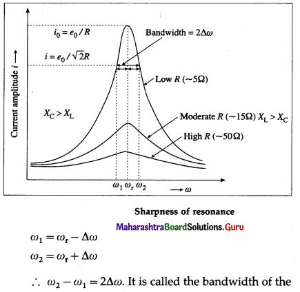
circuit. \(\frac{\omega_{\mathrm{r}}}{2 \Delta \omega}\) is a measure of the sharpness of resonance If It is high, resonance is sharp; if it is low, resonance is not sharp.
The sharpness of resonance Is measured by a coefficient called the quality or Q fader of the cicuit.
The Q factor of a series LCR resonant circuit is defined as the ratio of the resonant angular frequency to the diference in two angular frequencies taken on both sides of the angular resonant ‘frequency such that at each angular frequency the current amplitude becomes \(\frac{1}{\sqrt{2}}\) times the value at resonant frequency.
∴ Q = \(\frac{\omega_{\mathrm{r}}}{\omega_{2}-\omega_{1}}=\frac{\omega_{\mathrm{r}}}{2 \Delta \omega}=\frac{\text { resonant frequency }}{\text { bandwidth }}\)
Q-factor is a dimensionless quantity. The larger the Q-factor, the smaller is the bandwidth i.e., the sharper is the peak in the current It means the series resonant circuit is more selective in this case. from figure shows that the lower angular frequency side of the resonance curve is dominated by the capacitive reactance, the higher angular frequency side is dominated by the inductive reactance and resonance occurs ¡n the middle. This follows from the formulae, XL = ωL and XC = \(\frac{1}{\omega C}\). The higher the ω, the greater ¡s XL and smaller is XC. At ω = ωr, XL = XC.
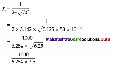
Question 50.
What Is the natural frequency of LC circuit with inductance 1H and capacitance µF?
Answer:
Question 51.
What is a choke coil? What is it used for? Explain.
Answer:
A choke coil is an inductor of high inductance. It consists of a large number of turns of thick insulated copper wire wound closely over a soft iron laminated cure- Average power consumed by it over one cycle is Pav = rrms irms cos Φ, where the power factor cos Φ = \(\frac{R}{\sqrt{R^{2}+\omega^{2} L^{2}}}\)
For ωL >> R. cos Φ is very low implying power consumption is reduced. The energy loss due to hysteresis in iron core is reduced by using a soft Iron core.
In an AC circuit a choke coil is used instead of a resistor to reduce power consumption In case of a pure resistor Pav is high as it is erms irms.
![]()
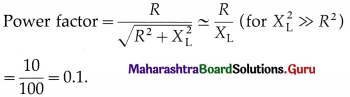
Question 52.
What is the approximate value of the power factor of a choke coil with R = 10 Ω and reactance = 100Ω ?
Answer:
53. Solve the following
Question 1.
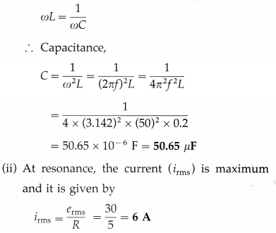
A coil of resistance S D and self-inductance 0.2 H is connected in series with a variable capacitor across a 30 V(rms) 50 Hz supply. At what capacitance will resonance occur? Find the corresponding current.
Solution:
Data: R = 5 Ω. L = 0.2 H, erms = 30 V. f = 50 Hz
Let C be the capacitance of the capacitor at resonance.
(i) At resonance,
Question 2.
An ac circuit consists of a resistor of 5 0 and an inductor of 10 mH connected In series with a 50 V
(peak)/50 Hz supply. What capacitance should be connected in series with the circuit to obtain maximum current? What will be the maximum current?
Solution:
Data: R = 50 Ω, L = 10 mH = 10 × 10-3 H, e0 = 50 V, f = 50 Hz
(i) Maximum current is obtained at resonance.
The condition for resonance is
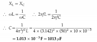
(ii) At resonance, Z = R
∴ Maximum current,
i0 = \(\frac{e_{0}}{Z}=\frac{e_{0}}{R}=\frac{50}{5}\) = 10 A
Question 3.
An LCR series combination has R = 10 Ω, L = 1 mH and C = 2 µF. Determine (i) the resonant frequency (ii) the current in the circuit (iii) voltages across L and C, when an alternating voltage of rms value 10 mV operating at the resonant frequency is applied to the series combination.
Solution:
Data : R = 10 Ω, L = 1 mH = 10-3 H, C = 2 × 10⁻⁶ F, erms = 10 mV = 10-2 V
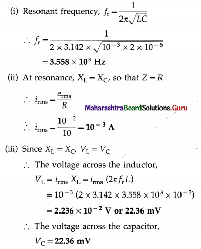
![]()
Question 4.
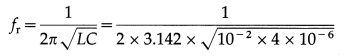
In a parallel resonant circuit, the inductance of the coil is 3 mH and resonant frequency is 1000 kHz. What is the capacitance of the capacitor in the circuit?
Solution:
Data : L = 3 mH = 3 × 10⁻³ Hz, fr = 1000 kHz = 1000 × 103 = 106 Hz
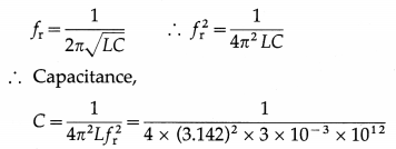
= 8.441 × 10⁻¹² F or 8.441 pF
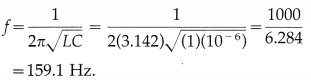
Question 5.
An ac circuit consists of an inductor of inductance 125 mH connected in parallel with a capacitor of capacity 50 µF. Determine the resonant frequency.
Solution :
Data : L = 125 mH = 0.125 H, C = 50 µF = 50 × 10-6 F
Resonant frequency,
= 63.65 Hz
Question 6.
An ac voltage of rms value 1V is applied to a parallel combination of inductor L = 10mH and capacitor C = 4 µF. Calculate the resonant frequency and the current through each branch at resonance.
Solution:
Data : erms = 1 V, L = 10 mH = 10-2H, C = 4 µF = 4 × 10⁻⁶ F
(i) Resonant frequency,
= 795.7 Hz
(ii) At resonance, the currents through the inductor and capacitor are in exact antiphase but equal in magnitude : iL = iC.
∴ iC = \(\frac{e_{\mathrm{rms}}}{X_{\mathrm{C}}}\) = (2πfrC) erms
= (2 × 3.142 × 795.7 × 4 × 10-6)(1) = 0.02A
Multiple Choice Questions
Question 1.
The motor of an electric fan has a self inductance of 10 H, and is connected to a 50-Hz ac supply in series with a capacitor. If maximum power transfer occurs when XL = XC, the capacitance of the capacitor is
(A) 0.5 µF
(B) 1 µF
(C) 10 µF
(D) 100 µF.
Answer:
(B) 1 µF
Question 2.
The reactance of a coil is 157 Ω. On connecting the coil across a source of frequency 100 Hz, the current lags behind the emf by 45°. The inductance of the coil is
(A) 0.25 H
(B) 0.5 H
(C) 4 H
(D) 314 H.
Answer:
(A) 0.25 H
Question 3.
In a series LCR circuit, the power factor at resonance is
(A) zero
(B) \(\frac{1}{2}\)
(C) \(\frac{1}{\sqrt{2}}\)
(D) 1.
Answer:
(D) 1.
![]()
Question 4.
The current in an LC circuit at resonance is called
(A) the displacement current
(B) the idle current
(C) the wattless current
(D) the apparent current.
Answer:
(C) the wattless current
Question 5.
In a series LCR circuit at resonance, the applied emf and current are
(A) out of phase
(B) in phase
(C) differ in phase by \(\frac{\pi}{4}\) radian
(D) differ in phase by \(\frac{\pi}{2}\) radian.
Answer:
(B) in phase
Question 6.
In a series LCR circuit, R = 3 Ω, XL = 8 Ω and XC = 4 Ω. The impedance of the circuit is
(A) 3 Ω
(B) 7 Ω
(C) 5 Ω
(D) 25 Ω
Answer:
(C) 5 Ω
Question 7.
A sinusoidal emf of peak value 150\(\sqrt {2}\) V is applied to a series LCR circuit in which R = 3 Ω and Z = 5 Ω. The rms current in the circuit is
(A) 30 A
(B) 30\(\sqrt {2}\) A
(C) 50 A
(D) 50\(\sqrt {2}\) A.
Answer:
(A) 30 A
Question 8.
In a series LCR circuit, R = 3 Ω, Z = 5 Ω, irms = 40 A and power factor = 0.6. The average power dissipated in the circuit is
(A) 2880 W
(B) 4800 W
(C) 8000 W
(D) 9600 W.
Answer:
(A) 2880 W
Question 9.
A parallel LC resonant circuit is used as
(A) a filter circuit
(B) a tuning circuit in a television receiver
(C) a transformer
(D) a rectifier.
Answer:
(A) a filter circuit
Question 10.
A senes LCR resonant circuit is used as
(A) a potential divider
(B) a tuning circuit in a television receiver
(C) a source of wattless current
(D) a radiowave trasmitter.
Answer:
(B) a tuning circuit in a television receiver
![]()
Question 11.
If AC voltage is applied to a pure capacitor. then voltage acrose the capacitor .
(A) leads the current by phase angle (\(\frac{\pi}{2}\)) rad
(B) leads the current by phase angle π rad
(C) lags behind the current by phase angle (\(\frac{\pi}{2}\)) rad
(D) lags behind the current by phase angle π rad.
Answer:
(C) lags behind the current by phase angle (\(\frac{\pi}{2}\)) rad
Question 12.
In a series LCR circuit at resonance, the phase difference between the current and emf of the source is
(A) π rad
(B) \(\frac{\pi}{2}\) rad
(C) \(\frac{\pi}{4}\) rad
(D) zero rad.
Answer:
(D) zero rad.
Question 13.
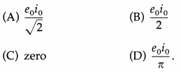
For e = e0 sin ωt, (average) over one cycle is
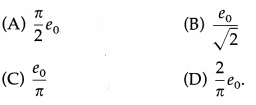
Answer:
(D) \(\frac{2}{\pi} e_{0}\)
Question 14.
For i = i0 sin ωt. irms/iav is
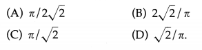
Answer:
(A) \(\frac{\pi}{2 \sqrt{2}}\)
Question 15.
If i = 10sin(314t) [in ampere). iav =
(A) 6.365 A
(B) 10/\(\sqrt{2}\) A
(C) 10/π A
(D) 5A.
Answer:
(A) 6.365 A
Question 16.
If e = 10 sin(400t) [in volt]. erms =
(A) \(\frac{10}{\pi}\) V
(B) \(\frac{10 \sqrt{2}}{\pi}\) V
(C) 5V
(D) 7.07V
Answer:
(D) 7.07V
Question 17.
In a purely resistive circuit, the heat produced by a sinusoidally varying AC over a complete cycle is given by H =
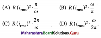
Answer:
(C) \(R\left(i_{\mathrm{rms}}\right)^{2} \cdot \frac{2 \pi}{\omega}\)
![]()
Question 18.
In a purely inductive AC circuit, i0 =
(A) \(\frac{e_{0}}{L}\)
(B) \(\frac{e_{0}}{\omega L}\)
(C) \(\frac{e_{0}}{f L}\)
(D) ωLe0.
Answer:
(B) \(\frac{e_{0}}{\omega L}\)
Question 19.
In a purely capacitive AC circuit, i0 =
(A) e0/C
(B) ωCe0
(C) e0/ωC
(D),fCe0.
Answer:
(B) ωCe0
Question 20.
The impedance of a series LCR circuit is
(A) R + (XL – XC)
(B) R + (XC – XL)
(C) \(\sqrt{R^{2}+\left(X_{\mathrm{L}}-X_{\mathrm{C}}\right)^{2}}\)
(D) \(\sqrt{R^{2}+X_{\mathrm{L}}^{2}-X_{\mathrm{C}}^{2}}\)
Answer:
(C) \(\sqrt{R^{2}+\left(X_{\mathrm{L}}-X_{\mathrm{C}}\right)^{2}}\)
Question 21.
In a purely inductive circuit, Pav =
Answer:
(C) Zero
Question 22.
In a series LCR AC circuit, power factor is
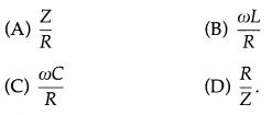
Answer:
(D) \(\frac{R}{Z}\)
![]()
Question 23.
The Q factor of an LCR series resonant circuit is
(A) resonant frequency/bandwidth
(B) bandwidth / resonant frequency
(C) ωr/(ω1 + ω2)
(D) (ω1 + ω2)/ ωr
Answer:
(A) resonant frequency/bandwidth
Question 24.
The power factor for a choke coil is
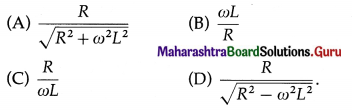
Answer:
(A) \(\frac{R}{\sqrt{R^{2}+\omega^{2} L^{2}}}\)
Question 25.
The power factor for a purely resistive AC circuit is
(A) 0.5
(B) 1
(C) \(\frac{1}{\pi}\)
(D) \(\frac{\pi}{2}\)
Answer:
(B) 1